| EXAMPLE 1 |
EXAMPLE 2 |
Requirements:
45 μH at 7.5 amps DC
(< 1% ripple current) |
Requirements:
45 μH at 7.5 amps DC
60μH max at 0 amps DC
(25% saturation max)
(<1 % ripple current) |
| Determine importance of the following design considerations: component size, temperature rise and cost. |
Example #1: Design Priorities
cost
temperature rise
component size |
Example #2: Design Priorities
component size
temperature rise
cost |
| Select appropriate materials to be considered. |
-26, -52 and -40 Materials should be
considered since the inductor
requirements do not limit swing and
these materials are the most cost effective. |
-8, -18, -28 and -33 Materials should
be considered because of the limited
swing requirements. |
| Calculate the required Energy Storage (1/2 LI2) |
| 1/2 LI2 = (1/2) (45) (7.5)2 = 1266 μJ |
1/2 LI2 = (1/2) (45) (7.5)2 = 1266 μJ |
| Select core size and shape |
-26 Material will be used in this example.
Refer to the Energy Storage Table in
Core Loss Increase Due to Thermal Aging,
(Figure 4). The T106 size toroid will be
selected in order to keep the winding
"simple" and the temperature rise around
25C°. The E137 is an attractive choice
if bobbin winding is preferred.
|
The -8 Material is the best choice since
component size is the primary concern.
The Energy Storage Table
Core Loss Increase Due to Thermal Aging,
(Figure 1), indicates that the T94 size toroid
is the smallest core able to meet the energy
storage requirements at < 40C° temperature
rise. We must also check the % saturation
curves found in theCore Loss Increase Due to Thermal Aging text to verify that this core will be
operating at less than 25% saturation. |
| Determine number of turns |
The curve at the top of page 40
indicates the T106 will require 217
ampere-turns to produce 1266 μJ.
Therefore,
NI = 162 / 7.5 = 29 turns
In the case of the E137 core, the curves
indicate that 162 ampere-turns will be
required to provide 1266 μJ.
Therefore,
NI = 162 / 7.5 = 22 turns
In the case of the T106 toroidal core,
the "simple" winding limits are close
estimates of typical single layer windings,
refer to the Single Layer Winding Table.
This table shows that #7 wire will fit in
a single layer and result in a 25C°
temperature rise from the wire. In the case
of the E137, referring to the "Full Winding" Table indicates that up to #13 wire can be used. |
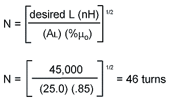
The curves in theCore Loss Increase Due to Thermal Aging text indicate that the T94 will be
operating at 84.5% of initial permeability (15.5% saturation) to produce 1266 μJ. Use the
following formula to calculate turns:

Since a "full" winding was required to
keep the temperature rise of the T94
below 40C°, refer to the "Full Winding" Table.
This table indicates that #16 wire should
be used.
This table also contains the information
necessary to calculate the DC resistance of a winding.
|
| Determine wire size |
Solution:
T106-26 with 29 turns #17
or E137-26 with 22 turns #14 |
Solution:
Part number T94-8/90
with 46 turns #16 |